
The step-by-step disassembly instructions presented here
apply to both the Stingray 1 and 2, and are a companion to our Maintenance, Cleaning
and Lubrication Guide. The only difference between the two Stingray
models is the barrel and top frame - the 'Ray 2 doesn't have a barrel shroud,
and thus has a different top frame. You can also refer to the Technical
Drawings for more information.
I highly recommend laying down an old towel to protect
your table, and to help keep round things from rolling away. Putting some
plastic (drop cloth, garbage bag, etc.) under the towel will protect the
work surface from getting oily. Use an old plastic margarine container,
egg carton, or similar container to put all the small parts in.
Tools Needed:
- 5/32" or 4mm allen wrench
- 3/16" pin punch, or #10 x 3" machine screw,
or 16 penney nail (with the tip ground flat)
- 1/8" pin punch, or #6 x 3" machine screw, or
8 penney nail (with the tip ground flat)
- 1/16" pin punch, or 1/16" rod or nail, or awl
- Small hammer
- Pliers
- Dental pick or small screwdriver
- Large screwdriver or old butter knife
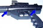
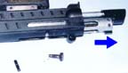
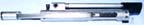
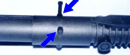
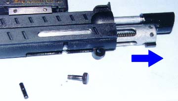
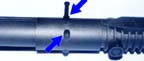 Step 1: Begin by removing the plastic pins that hold in the aluminum barrel
and plastic shroud on the 'Ray 1, or the aluminum barrel only on the 'Ray
2. If the pins are tight, you can push them out from the other side with
a 5/32" allen wrench or 3/16" pin punch. You may need to tap lightly
with a hammer. Note: Some 'Rays have quick strip pins with rings
which pull out easily. Step 1: Begin by removing the plastic pins that hold in the aluminum barrel
and plastic shroud on the 'Ray 1, or the aluminum barrel only on the 'Ray
2. If the pins are tight, you can push them out from the other side with
a 5/32" allen wrench or 3/16" pin punch. You may need to tap lightly
with a hammer. Note: Some 'Rays have quick strip pins with rings
which pull out easily. |
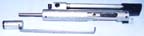
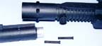 The barrel and shroud
('Ray 1) or barrel ('Ray 2) should pull right out. It may be stuck with
dirt and/or dried paint goo, but a gentle side to side motion should work
it free. If only the shroud on the 'Ray 1 comes out, no problem. Pull the
shroud all the way off, then pull out the barrel. The barrel and shroud
('Ray 1) or barrel ('Ray 2) should pull right out. It may be stuck with
dirt and/or dried paint goo, but a gentle side to side motion should work
it free. If only the shroud on the 'Ray 1 comes out, no problem. Pull the
shroud all the way off, then pull out the barrel. |
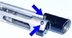
 Step 2: Remove the plastic pins that hold the grip frame to the top frame.
If they're tight, you can push them out from the other side with a 5/32"
allen wrench or 3/16" pin punch. You may need to tap lightly with a
hammer. Note: Some 'Rays have quick strip pins with rings which pull
out easily. After the pins are out, pull the grip frame and top frame apart. Step 2: Remove the plastic pins that hold the grip frame to the top frame.
If they're tight, you can push them out from the other side with a 5/32"
allen wrench or 3/16" pin punch. You may need to tap lightly with a
hammer. Note: Some 'Rays have quick strip pins with rings which pull
out easily. After the pins are out, pull the grip frame and top frame apart. |
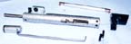
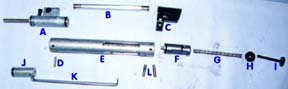
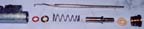
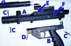 This is what you should
have so far: This is what you should
have so far:
A - top frame; B - grip frame; C - retaining pins, long;
D - retaining pin, short; E - top frame pin; F - cocking screw; G - barrel
and shroud
Remember, if you have a 'Ray 2, you'll have just an aluminum
barrel, without the plastic shroud. |
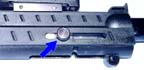 |
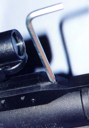
Step 3: Remove the cocking screw
by turning it counter clockwise. (Righty tighty, lefty loosey!) If it's
stubborn, use a pair of pliers to loosen it. Wrap a rag around it first,
to protect it from the pliers. |
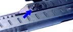 |
Step 4: From either side, using
your 3/16" pin punch (or #10 x 3" machine screw, or 16 penney
nail) and hammer, tap out the pin that holds the valve and tube assembly
in place. |
 |
Step 5: Lay the top frame on the
table, and carefully slide out the valve and tube assembly. |
 |
If the valve and tube assembly doesn't want to slide out,
the velocity screw may be holding it in. Using your 5/32" allen wrench,
screw the velocity screw in a few turns. |
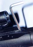
 To remove the detent
ball, you'll need to push out the roll pin which holds in the detent cap.
Using a 1/16" pin punch (or nail or awl), push the pin from one side
until you can pull it out with pliers. Put a finger over the cap before
fully removing the pin, or you'll lose parts. When the pin is out, very
carefully remove the cap, spring, and ball. To remove the detent
ball, you'll need to push out the roll pin which holds in the detent cap.
Using a 1/16" pin punch (or nail or awl), push the pin from one side
until you can pull it out with pliers. Put a finger over the cap before
fully removing the pin, or you'll lose parts. When the pin is out, very
carefully remove the cap, spring, and ball. |
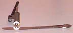
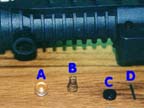 Here are the detent
parts: Here are the detent
parts:
A - detent ball (the stock ball is steel, not the acrylic
which is shown); B - detent spring; C - detent cap; D - detent pin |
 When reassembling the
detent assembly, put the ball in first, then make sure the large end of
the spring goes against the ball. Caerfully hold the cap in place with a
finger, line up the holes, and push the pin through. You may have to work
with it a bit to get the pin to go all the way through. A little finesse
is called for here. When reassembling the
detent assembly, put the ball in first, then make sure the large end of
the spring goes against the ball. Caerfully hold the cap in place with a
finger, line up the holes, and push the pin through. You may have to work
with it a bit to get the pin to go all the way through. A little finesse
is called for here. |
 |
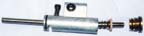
Here is the valve and tube assembly. If any pins fell out
after you removed it, that's okay. Just don't loose them! |
 |
Step 6: Remove the bolt by lifting
the transfer link out of the slot in the hammer, and sliding the bolt forward
off the bolt guide. |
 |
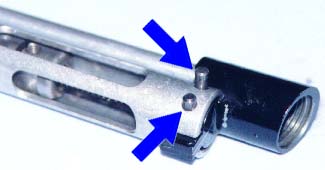
Step 7: Remove the pins that hold
the donkey (CA adapter) in place. They may have already fallen out, or they
might fall out with a little gentle pushing and pulling on the donkey. If
not, tap them out with your 3/32" allen wrench or 1/8" pin punch. |
 |
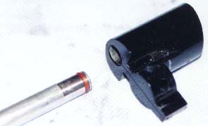
Pull the donkey out. The transfer tube will probably stay
in either the donkey or the valve - go ahead and pull it out. |
 |
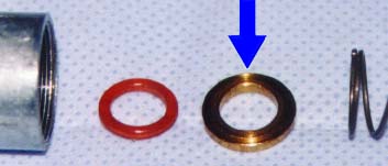
The donkey and one end of the transfer tube. The urethane
o-ring on the transfer tube can be clearly seen. |
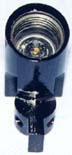 |
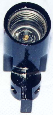
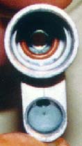
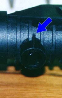
The "business" end of the donkey. This is where
the CO2 tank screws in. You can see the brass colored depressor pin inside.
The depressor pin is what depresses the pin valve on the CO2 tank. |
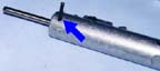 |
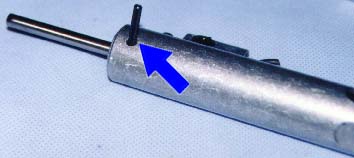
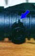
Step 8: Remove the valve pin.
This pin may have already fallen out, or it might fall out with a little
gentle pushing and pulling on the valve. If not, tap it out with your 3/32"
allen wrench or 1/8" pin punch. |
 Slide the valve out in the
direction of the arrow. If it's stuck, do NOT use pliers on the bolt guide.
Instead, push it out, after you've removed the hammer and spring (see below).
Or, using a wooden dowel or the handle of your scredriver, tap gently on
the back of the valve housing where it sticks through the top of the hammer
tube (opposite the velocity screw). Slide the valve out in the
direction of the arrow. If it's stuck, do NOT use pliers on the bolt guide.
Instead, push it out, after you've removed the hammer and spring (see below).
Or, using a wooden dowel or the handle of your scredriver, tap gently on
the back of the valve housing where it sticks through the top of the hammer
tube (opposite the velocity screw). |
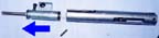
 Step
9: Push out the hammer, spring, and spring guide.
There may be a little resistance. If the valve is out, you can push the
parts out in the direction of the arrow, with a long screwdriver or piece
of dowel. Or, carefully push the spring and guide out by putting a screwdriver
tip in the slot in the hammer (bottom photo), and pushing them out. The
hammer should then come right out. Step
9: Push out the hammer, spring, and spring guide.
There may be a little resistance. If the valve is out, you can push the
parts out in the direction of the arrow, with a long screwdriver or piece
of dowel. Or, carefully push the spring and guide out by putting a screwdriver
tip in the slot in the hammer (bottom photo), and pushing them out. The
hammer should then come right out. |
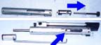
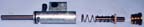
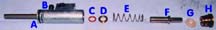
 Here
are all the parts you've taken out of the valve tube assembly: Here
are all the parts you've taken out of the valve tube assembly:
A - valve assembly; B - transfer tube; C - donkey; D -
valve pin; E - valve tube; F - hammer; G - hammer spring; H - hammer bumper;
I - spring guide; J - bolt; K - bolt transfer link; L - donkey pins |
 |
Step 10: Using your butter knife
or large screwdriver, remove the valve retainer by turning it counter clockwise.
Careful, it's spring loaded! |
 |
After the valve seal retainer is loose, remove it slowly by
hand, being careful not to let the valve stem shoot out. |
 |
The valve stem, seal, and spring should slide out easily. |
 |
There are two parts down inside the valve housing, the washer
and o-ring. Carefully pull them out, using a dental pick, or small screwdriver. |
 Here
are all the parts you've taken out of the valve assembly: Here
are all the parts you've taken out of the valve assembly:
A - valve body/bolt guide; B - velocity screw; C - urethane
o-ring; D - valve washer; E - valve spring; F - valve stem; G - valve seal;
H - valve seal retainer |
 |
When reassembling, make sure the urethane o-ring is seated
in the groove down inside the valve housing. |
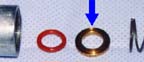 |
One side of the valve washer has a ridge on it. Make sure,
when reassembling, that the ridge side goes in first (towards the o-ring). |
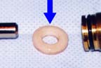 |
When putting the valve seal back on the valve stem, make sure
the ridge on the seal faces the brass retainer. |
Obviously, reassembly is the reverse of disassembly. Just
follow the disassembly directions backwards, and you'll get it all back
together!

© Stingray Toters INternet Group
 Step 1: Begin by removing the plastic pins that hold in the aluminum barrel
and plastic shroud on the 'Ray 1, or the aluminum barrel only on the 'Ray
2. If the pins are tight, you can push them out from the other side with
a 5/32" allen wrench or 3/16" pin punch. You may need to tap lightly
with a hammer. Note: Some 'Rays have quick strip pins with rings
which pull out easily.
Step 1: Begin by removing the plastic pins that hold in the aluminum barrel
and plastic shroud on the 'Ray 1, or the aluminum barrel only on the 'Ray
2. If the pins are tight, you can push them out from the other side with
a 5/32" allen wrench or 3/16" pin punch. You may need to tap lightly
with a hammer. Note: Some 'Rays have quick strip pins with rings
which pull out easily.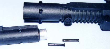 The barrel and shroud
('Ray 1) or barrel ('Ray 2) should pull right out. It may be stuck with
dirt and/or dried paint goo, but a gentle side to side motion should work
it free. If only the shroud on the 'Ray 1 comes out, no problem. Pull the
shroud all the way off, then pull out the barrel.
The barrel and shroud
('Ray 1) or barrel ('Ray 2) should pull right out. It may be stuck with
dirt and/or dried paint goo, but a gentle side to side motion should work
it free. If only the shroud on the 'Ray 1 comes out, no problem. Pull the
shroud all the way off, then pull out the barrel.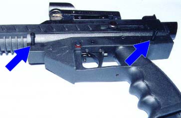 Step 2: Remove the plastic pins that hold the grip frame to the top frame.
If they're tight, you can push them out from the other side with a 5/32"
allen wrench or 3/16" pin punch. You may need to tap lightly with a
hammer. Note: Some 'Rays have quick strip pins with rings which pull
out easily. After the pins are out, pull the grip frame and top frame apart.
Step 2: Remove the plastic pins that hold the grip frame to the top frame.
If they're tight, you can push them out from the other side with a 5/32"
allen wrench or 3/16" pin punch. You may need to tap lightly with a
hammer. Note: Some 'Rays have quick strip pins with rings which pull
out easily. After the pins are out, pull the grip frame and top frame apart.

 To remove the detent
ball, you'll need to push out the roll pin which holds in the detent cap.
Using a 1/16" pin punch (or nail or awl), push the pin from one side
until you can pull it out with pliers. Put a finger over the cap before
fully removing the pin, or you'll lose parts. When the pin is out, very
carefully remove the cap, spring, and ball.
To remove the detent
ball, you'll need to push out the roll pin which holds in the detent cap.
Using a 1/16" pin punch (or nail or awl), push the pin from one side
until you can pull it out with pliers. Put a finger over the cap before
fully removing the pin, or you'll lose parts. When the pin is out, very
carefully remove the cap, spring, and ball.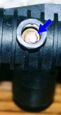 When reassembling the
detent assembly, put the ball in first, then make sure the large end of
the spring goes against the ball. Caerfully hold the cap in place with a
finger, line up the holes, and push the pin through. You may have to work
with it a bit to get the pin to go all the way through. A little finesse
is called for here.
When reassembling the
detent assembly, put the ball in first, then make sure the large end of
the spring goes against the ball. Caerfully hold the cap in place with a
finger, line up the holes, and push the pin through. You may have to work
with it a bit to get the pin to go all the way through. A little finesse
is called for here.